

Kitchen Window Seat
Creating a space that is playful, functional and attractive requires a quite a bit of planning and thought. The kitchen is a great place to socialise and hang out and when you have a window as a focal point the possibilities are endless. Here's how we created ours.
1. Design
Below are the design aspects and considerations that formed a foundation for the design
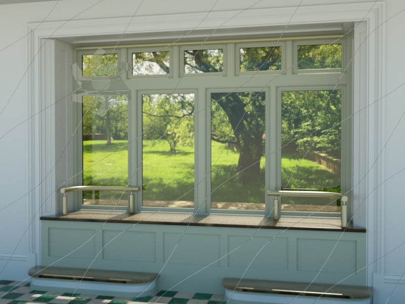
- The window cill is intended to be used as an area to perch and interact with people in the kitchen.
- The central windows open outward creating a space to pass things through and into the garden.
- Blinds will be used to shield the room from the intense sunny periods of the day.
- Lighting will be incorporated into the head of the bay.


The final design considered
- The ease of construction and proportions for the joinery reveals and paneling.
- The incorporation of an electrical roman blind.
- A seating design that encourages people to sit comfortably in the bay.
- A pleasing arrangement of night lighting.
- An easy to remove step design for the easy facilitation of cleaning
- A mix of modern and traditional styles
2. Construction Drawings
Drawings were produced to calculate the quantity of material required to create the window seat joinery. The drawings then act as a way to identify and produce the multiple components.


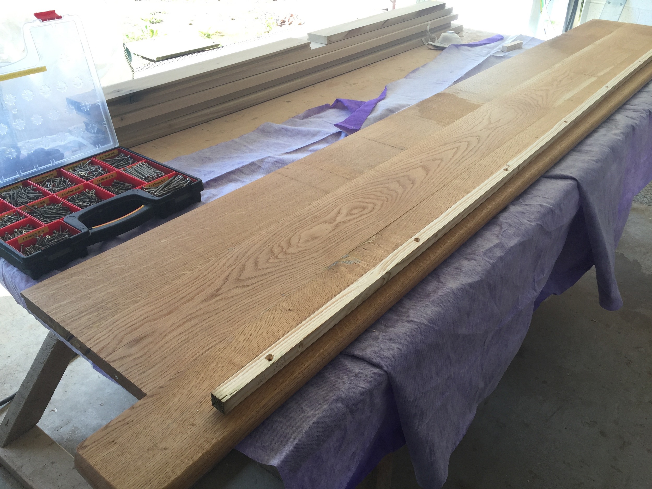
3. Production
The timber goes through the usual production process of marking, cutting, making square, thicknessing, profiling, jointing, gluing, sanding and painting.


4. Installation
Making sure fixings don't show on the surface and all the components are level, plumb and secure is an art of its own.
Here's how we did it -
1. A piece of structural timber was fixed level to the front of the seat. This gave both a support for the oak board and a medium to both secure and locate the position of the window board. A fixing strip was then applied to the underside of the oak board giving a fixing solution that would be hidden.
2. For the lower panels a rebate was taken from the front surface. A t-shaped component (See drawing below) was fixed to the wall with its landings level with the strip mounted under the cill, this gave two points to locate the lower panel, the top of the panel was fixed with screws that were then plugged. The bottom edge of the top panel and the upper edge of the lower panel were fixed back with a capping strip.


3. The reveal panels were the final parts to put into place. Starting with the top panel, then the rear side panels finished with the front side panels. The side panels were fixed with a shaped softwood strip which could be fitted with as few fixings showing on the surface as possible.

4. Subsequent to the reveal components being trial fitted they were removed to allow the installation of the wiring for both the integrated led lighting and electric blinds and to make the painting process more convenient.

